Selecting The Right Cable Size For Your Battery Bank
Are you putting together a battery bank for an alternative energy system? Or just wondering what gauge wire to connect 12 volt batteries?
Maybe you’re trying to determine the correct size of interconnecting cables between the batteries themselves and the charger / inverter.
How big should the cables be? What size? More accurately, what gauge (AWG)?
Read on… or go straight to the chart (AWG gauge versus Amps) at bottom of page.
The short answer (regardless of your application) is to know the maximum potential current (Amps) that will flow through the interconnecting circuit – based on your schematic. Therefore, there’s no quick and correct answer. It depends…
I recommend getting yourself a clamp meter that measures DC current! This will help verify what’s actually going through your cables! The following multi-meter clamp meter will measure up to 400 Amps.
Klein Tools Digital Clamp Meter
(view on amzn)
The Battery Bank
A battery bank for an Off-Grid solar powered alternative energy system will consist of a number of batteries and their interconnecting terminal cables.
The batteries will be connected together in various series-parallel configurations depending on your schematic design to achieve a desired voltage and capacity to work best with the inverter (and charger).
The batteries will serve as a energy storage center to deliver power during periods when the solar panels themselves are either in the dark or under-delivering due to weather conditions.
I’m not going to get into recommendations for series-parallel battery wiring (another article). However I will cite my own current configuration as an example:
My System as an example…
All 24 batteries are 12 volt 100 AH rated. There are 6 series strings (of 4 each) that are all connected in parallel to comprise a battery bank of 48 volts @ 600 AH. That’s a total capacity of 28.8 KwH, although 14.4 KwH is safely usable (50% max). That said, my rule of thumb is to avoid draining more than 30% off the top for lead acid batteries…so that gives me just about 10 KwH to play with.
[ Read: How To Calculate Ah (Amp Hours) and Wh (Watt hours) Of A Battery Bank ]
This, combined with almost 4,000 watts of PV panels has been enough to supply basic power and essential systems energy needs within my modest home. My electrical needs are low to begin with, but I do have to watch it and reduce loads especially during the Fall and Winter months. Unless your system is enormous (and enormously expensive) you will have to keep an eye on things anyway…
I have integrated the ability to balance (select) my individual loads to be sourced from either ‘grid’ or ‘solar/batteries/inverter’. I’ve installed two (Reliance Controls) 10-circuit transfer switch boxes for 20 circuits from my mains panel. It makes the system entirely 100% flexible for balancing loads and demands throughout the year.
My Reliance Controls A510C transfer switches shown below. 10 circuits each. I installed two of them. Gives me great control over balancing seasonal load differences and PV system variances due to weather and seasons.
DC Cable Size Between Connections
How big should the cables be?
First you will need to calculate the maximum current that could flow through the various interconnecting cables before you choose the proper cable size.
Cables must be sized to carry the maximum load that the system could deliver. Undersized cables will result in overheating, and even melted connections. Worse yet, it could become a potential fire hazard.
There are three maximum DC current specifications to figure out:
1. DC Charger charging current (charger to battery bank).
2. DC Load demand from the inverter (battery bank to inverter).
3. DC current flow within the battery bank interconnects.
Battery Charger – Max Current
My solar battery charger is the ‘Midnite Solar Classic 200’.
According to its specifications, the maximum charge that it can put to the battery bank at 48 volts is 74 amps (~ 3500 watts). Use the chart below to choose cable size. Give yourself a nice margin!
Inverter – Max Battery Current
My inverter is an Outback VFX 3648.
According to its specifications, the maximum overcurrent ampacity is 175 amps and they call for a OBCD-175 breaker on the DC side. Evidently there’s a built-in surge handling capability on the DC side to 175 amps.
The inverter only puts out 3600 watts max, which would be around 75 amps off the 48-volt battery bank for normal max operation. But given the inverter’s over-current rating, I had to go with sizing that cable for 175 amps.
So I chose 00 (2/0) AWG for this portion of the overall circuit.
Maximum Current Within the Battery Bank
You will need to determine how many amps will flow through interconnecting cables of the battery bank. This involves some basic understanding of series-parallel wiring and how it affects volts and amps. I will assume you have that basic understanding… (e.g. Ohms Law)
First, we know that in my example there may be up to 175 amps pulled from the battery bank (worst case scenario). However I have 6 series-strings of batteries all in parallel, so only one sixth of the maximum will flow through any one string as the strings share the load. So that works out to be around 30 amps (of worst case over-current max) flowing through each of the six strings.
That said, I try not to live on the edge, and always oversize with a margin.
Actually, for my present installation, I’ve sized all of my DC cables to meet the 175 amp worst case scenario. Because I had the cable. So all interconnecting cables are 00 (2/0) AWG based on the chart below. However, I didn’t need them to be that big. Read on…
My interconnecting cables within my battery bank… I ended up making my own after buying some pre-made. This saved some money. I did need 00 (2/0) AWG for the main trunk, but went WAY overboard on my series-strings interconnects. I used the same cable (because I had bought it in bulk). Instead I could’ve used something like 6 AWG, even with a 50% margin. Oh well… at least there’s no worries with the 2/0 !
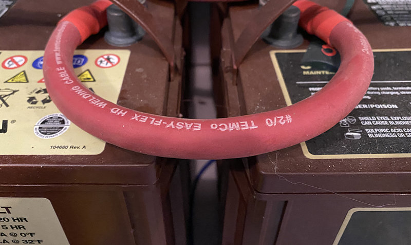
Note: Again, the cable size in the photo above is way ‘overkill’ for my series/parallel wiring of my 48 volt battery bank comprised of 24 12-volt batteries. I had the cable, and, it sure makes for extremely low cable resistance (grin)…
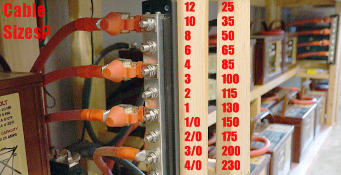
Cable Size Ampacity Chart
The following maximum amps versus cable size (AWG) come from the NEC version 2011. As far as I know these values are valid as of today. For more detail though, check with the National Electrical Code as well as your own zoning laws.
Note: I would NEVER design interconnecting cable size anywhere near its maximum amps! That’s too hot for me! Heat loss equals efficiency loss! Give yourself a wide margin.
– Copper Conductor Ampacity based on 75°C (167°F) reference
– Cable Types: RHW, THHW, THW, THWN, XHHW, USE, ZW
| Cable Size (AWG – Gauge) | Amps – Ampacity |
| 14 AWG | 20 |
| 12 AWG | 25 |
| 10 AWG | 35 |
| 8 AWG | 50 |
| 6 AWG | 65 |
| 4 AWG | 85 |
| 3 AWG | 100 |
| 2 AWG | 115 |
| 1 AWG | 130 |
| 0 (1/0) AWG | 150 |
| 00 (2/0) AWG | 175 |
| 000 (3/0) AWG | 200 |
| 0000 (4/0) AWG | 230 |
Make Your Own Battery Interconnect Cables?
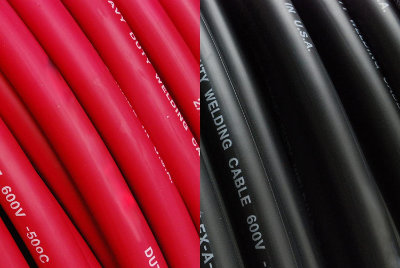
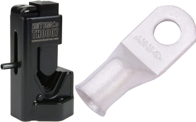
Eventually I decided to do-it-yourself for making heavy duty cables for my battery bank. I purchased bulk cable (just pick your size). And a heavy duty cable crimper (and the associated wire lugs).
Temco Bulk Cable
(view on amzn)
Temco Hammer Lug Crimper
Wire Lugs – Eyelets
[ Read: Battery State of Charge Chart ]
[ Read: The Four Essentials of Off Grid Solar ]